Introduction
Cytron send me a new product, Robo Pico (link) together with Pico W (link2) for review and here are the essential summary.
Unboxing & PCB layout
- the box comes with Robo Pico purple board
- 4 x grove cables to 4 female dupont
- cute mini screw driver
- nice purple soldermask PCB
Flexible power options + battery charging
- USB Micro from the Pico/Pico W
- DC-in ( 3.6 - 6V ) ( green screw terminals )
- single cell LiPO/Li-Ion battery ( ph2.0 connector )
- Built-in 1-cell charger to charge the battery when USB is plugged in.
- On / Off switch
Available Ports
- 2 x 20 ways female headers for Pi Pico/W
- 1 x reset button ( *** )
- 2 x channel DC motor driver
- 4 x servo motor ports
- 4 x motor quick test buttons
- 2 x user buttons
- 7 x grove ports
- 1 x maker port ( Qwiic / STEMMA QT / JST SH-4 )
- 13 x LED indicators on all the non-power grove ports
- 2 x RGB LED WS2812B/NeoPixels
- 1 x piezo buzzer
- on/off switch
Reviews & Sample Project
Being an Arduino site, I will do this review using Arduino framework with the following using the Raspberry Pi Pico / RP2040 by Earle Philhower ( arduino-pico ) and the documentation are located here https://arduino-pico.readthedocs.io/en/latest/
Since this comes with a Pico W with headers (link2), I decided to do a web controlled Servo + RGB LED using a slider.
I have hookup 2 x servo motors to GPIO14 and GPIO15 and a 18650 battery with a PH2.0 connector to the battery port.
This is the first time I m using the Pico W but I have been using Pico in my past project before. The amazing thing is ALL the past Wifi examples ( mostly from ESP32 ) JUST WORKS without any modifications to the source codes. If you are unsure which Pico to get, get the Pico W for future expandions.
The major differences between Pico and Pico W is that the Pico built-in LED is on GPIO25 where the Pico W have the GPIO25 driving the Wireless module.
I am utilizing the 8 blue LED ( above the 5 grove connectors ) as a left or right car signal indicator animations when the servo is turning to the left or right.
When the servo is turning left, the rows of blue LED will animate a left signal turn and then the servo is turning right, it will do the right signal animation.
The video for this review is located at www.tiktok.com/@stanleyseow/
Here is the source code at https://pastebin.com/ZARAa14L
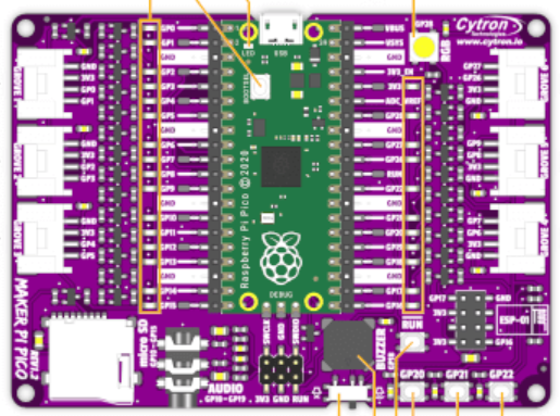
Compared to Maker Pi Pico
Robo Pico :
- Have 2 x DC Motor drivers
- Have 4 x Servo motors pins
- Battery port and charging circuit
- 1 x Maker port ( Qwiic / STEMMA QT / JST SH-4 )
Maker Pi Pico :
- SDcard slot
- L/R audio output
- 1 less WS2812B RGB LED
Summary Links
- Robo Pico https://my.cytron.io/p-robo-pico-simplifying-robotics-with-raspberry-pi-pico
- Pico W https://my.cytron.io/p-raspberry-pi-pico-wireless-board-smd-presoldered-headers
- Arduino Pico Framework https://github.com/earlephilhower/arduino-pico
- Arduino Pic Docs https://arduino-pico.readthedocs.io/en/latest/
- Source code https://pastebin.com/ZARAa14L
- Robo Pico Video demo www.tiktok.com/@stanleyseow
- related Maker Pi Video 1 www.tiktok.com/@stanleyseow
- related Maker Pi Video 2 www.tiktok.com/@stanleyseow


No comments:
Post a Comment