Saturday, July 1, 2023

Cytron Robo Pico review

Introduction


Cytron send me a new product, Robo Pico (link) together with Pico W (link2) for review and here are the essential summary. 

Unboxing & PCB layout

  • the box comes with Robo Pico purple board
  • 4 x grove cables to 4 female dupont
  • cute mini screw driver
  • nice purple soldermask PCB
This Printed Circuit Board (PCB) is well designed with CLEAN and CLEAR labels on front and back of PCB. All pins  are CLEARLY labeled without the need to refer to the documentations. I really ike the flexible power options to power up this board from USB, DC in and also Li-Ion battery + charging options al bult-in.


Flexible power options + battery charging

  • USB Micro from the Pico/Pico W
  • DC-in ( 3.6 - 6V ) ( green screw terminals )
  • single cell LiPO/Li-Ion battery ( ph2.0 connector )
  • Built-in 1-cell charger to charge the battery when USB is plugged in.
  • On / Off switch


Available Ports


  • 2 x 20 ways female headers for Pi Pico/W
  • 1 x reset button ( *** )
  • 2 x channel DC motor driver
  • 4 x servo motor ports
  • 4 x motor quick test buttons
  • 2 x user buttons
  • 7 x grove ports
  • 1 x maker port ( Qwiic / STEMMA QT / JST SH-4 ) 
  • 13 x LED indicators on all the non-power grove ports
  • 2 x RGB LED WS2812B/NeoPixels
  • 1 x piezo buzzer
  • on/off switch

Reviews & Sample Project

Being an Arduino site, I will do this review using Arduino framework with the following using the Raspberry Pi Pico / RP2040 by Earle Philhower ( arduino-pico ) and the documentation are located here https://arduino-pico.readthedocs.io/en/latest/

Since this comes with a Pico W with headers (link2), I decided to do a web controlled Servo + RGB LED using a slider.

I have hookup 2 x servo motors to GPIO14 and GPIO15 and a 18650 battery with a PH2.0 connector to the battery port.


This is the first time I m using the Pico W but I have been using Pico in my past project before. The amazing thing is ALL the past Wifi examples ( mostly from ESP32 ) JUST WORKS without any modifications to the source codes. If you are unsure which Pico to get, get the Pico W for future expandions.

The major differences between Pico and Pico W is that the Pico built-in LED is on GPIO25 where the Pico W have the GPIO25 driving the Wireless module.

I am utilizing the 8 blue LED ( above the 5 grove connectors ) as a left or right car signal indicator animations when the servo is turning to the left or right.

When the servo is turning left, the rows of blue LED will animate a left signal turn and then the servo is turning right, it will do the right signal animation.

The video for this review is located at www.tiktok.com/@stanleyseow/

Here is the source code at https://pastebin.com/ZARAa14L

Compared to Maker Pi Pico


Robo Pico :

  • Have 2 x DC Motor drivers
  • Have 4 x Servo motors pins
  • Battery port and charging circuit 
  • 1 x Maker port ( Qwiic / STEMMA QT / JST SH-4 ) 
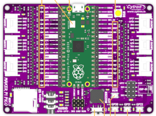
Maker Pi Pico :

  • SDcard slot
  • L/R audio output
  • 1 less WS2812B RGB LED

Summary Links


Contact Info 


Tuesday, February 21, 2023

Introduction to FPGA for Makers


For hobbyist and makers, exploring FPGA ( Field Programmable Gate Array ) is a major milestones as a maker. My experience with FPGA was when I was working for a web acceleration company that uses FPGA to accelerate web connections and DDoS prevention. 

My reasons to start exploring FPGA was when I was designing a hardware that requires me to support multiple hardware and sensors and ability to detect and use those hardware seemlessly.

As a maker, we always find the lowest cost method to get the best bang for the buck and secondly, it MUST be open source and not using any proprietary software as much as possible.

While exploring and searching for my FPGA, several FPGA brands appear quite often like Xilinx, Altera and Lattice. After much more digging, I found out that Lattice have very good support for open source hardware as they were the smallest of the 3 trios.

A few FPGA development boards caught my attention and one was really interesting ( and low cost too ), it was actually a LED Driver ( read more details in the link) called ColorLight 5A-75B with a Lattice ECP5 with 25k LUT, lots of pins, 2 x Gigabit Ethernet and external RAM. The reason I like this FPGA board is because during that time, I was also exploring and driving LED Panels with 64x64 pixels.

ColorLight 5A-75B

After some trial and errors, I managed to program the ColorLight to drive an actual 64x64 LED Panels. First time successfully program a FPGA.

ColorLight with LED Panels

The ColorLight was program using a FT2232 board that comes with 2 UART ports and commonly used in Lattice official development board.


FT2232 with ColorLight

One of the major drawback of this FPGA board - ColorLight was that it can ONLY have output ports and only 1 input port for the build-in button at the corner. that was because it was specially made to drive 5V LED Panels, 8 of them while accepting video input from the gigabit ethernet ports from the video server.

Many hardware hackers did a lot of hacking on this board like below :-

Lots of details here ( your starting point at first link )


After ordering the chips listed by the tweet, I proceed to swap out the 74HC245 with the bi-directional chip. The part number is SN74CBT3245APW


With some hotair, I pasted some kapton take to protect the plastic parts, the 74HC245 come off easily. After cleaning up the pads, I proceed to solder the new FET to the pads. Lets try with some solderpaste as the pins are very small and close together.


After blowing hotair, those solderpaste becomes a big solder bridge and I use a wick to suck up all excess solder on the pins. The results was good but just too much work. For the second chip, I just directly apply solder and and wick all the excess solder on the pins.


Here is the results after soldering two chips to the board. 

*** The input voltage must be lowered using a diode to 4.3V from 5V

After a successful test that the pins can support both input and output, I switch to use icestudio from fpgawars to program the FPGA using a graphical flow based interface with apio.


icestudio


Above is the final picture with 8-DIP switches pmod as input and 8-LED tristate pmod as output.

summary Links
  • https://hackaday.com/2020/01/24/new-part-day-led-driver-is-fpga-dev-board-in-disguise/#more-395868
  • https://github.com/q3k/chubby75/tree/master/5a-75b
  • https://github.com/FPGAwars/icestudio


LinkWithin

Related Posts Plugin for WordPress, Blogger...