Monday, December 14, 2020

QMK flashing and coding the SVT RGB 4x4 dumbpad

After more a week, the two black PCB sent for fabrications was finally back. Time to do some SMD soldering and figuring out on how to program the keyboard to work.

The RGB SVT source codes at Summary Links below.


SVT RGB dumbpad (front)

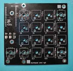
SVT RGB dumbpad (back)

QMK firmware

The Quantum Mechanical Keyboard ( QMK ) is an open source community centered around developing computer input devices. ( Text copied directly from QMK site )

It support a few commonly used micro-controller like Atmel atmega32u4, Freescale Teensy  and STM32 families of micro-controllers. For my case, the Pro Micro uses the Atmel atmega32u4, a popular choice for Arduino that can emulate a keyboard / HID devices.

As I am just a fork of the dumbpad keyboard, I will also just need to modify the same keyboard by modifying the keymaps and config files only. The QMK does NOT use the Arduino IDE.

As my primary computer runs on Win 10 , I will choose the Windows development tools and downloaded the following software. 

  • QMK Toolbox
  • MSYS2
  • VSCode ( I already have this ) 

The MSYS2 installation was not as straight-forward as I expected but after a few trial and errors, installing and re-installing Python, I found the missing piece. Open a MinGW 64-bit Terminal, I repeat, a MinGW 64-bit Terminal.

Once everything was setup successfully, it is time to do some code editing.

git clone the qmk firmware from github.
Go to the keyboard/dumbpad folder and open the config.h file, edit it with your favorite text editor.

Figuring out the LED pins


As the pins are following the Atmel port pins instead of the Arduino digital pins, I have to map this according to the LED I connected to the Pro Micro.

I was using port B6 as LED0 and port B1 as LED1
LED2 at port B3 is shared between LED2 or RGB LED pin.

I also noticed there are two extra on-board LED at port B0 and port D5, let's configure them as well. As the Pro Micro is facing downwards, the two on-board LED, will only shine downwards and not very useful in every use.


Below are the config.h for the LEDs

/* LED layer indicators */

// Using external LED for layers indicator

 #define LAYER_INDICATOR_LED_0 B6 // Red

 #define LAYER_INDICATOR_LED_1 B1 // Blue or Green

 // On-board LED for debugging

    #define LAYER_INDICATOR_LED_2 B0

    #define LAYER_INDICATOR_LED_3 D5


The next pin are the most exciting one, the RGB pins as below, you need to state the pin number and the number of LEDs on the LED strip. As I run them in mirror mode ( Both LED strip will display the same patterns, I just indicate 4 as the number of LEDs )

    #define RGB_DI_PIN B3

    #ifdef RGB_DI_PIN

    #define RGBLED_NUM 4

The rest of the RGB animations / patterns can be customized according to your own needs. 


Rotary Encoder

The next pins to configure is the rotary encoder, the dumbpad keyboard support TWO rotary encoder, I got both encoder working but the final version, I will only use one encoder.

I m using ENCODER0 connected to port D4 and B2.
ENCODER1 (unsued) is connected to port port D0 and D1

/* Rotary encoder */
// D1, D0 is right encoder
// D4, B2 is left encoder
#define ENCODERS_PAD_A { D4 } 
#define ENCODERS_PAD_B { B2 }

Once all the config.h pin definition is done, I make a copy of the default keymap folder for my keyboard, I called it svt_numpad


Key Mappings

Edit the keymap.c file, the default already have all the keys mapped.

From here, you can change the keys according to the documentation from QMK here.

https://beta.docs.qmk.fm/using-qmk/simple-keycodes/keycodes_basic

RGB stuff here 

https://beta.docs.qmk.fm/using-qmk/hardware-features/lighting/feature_rgblight

  /*
        BASE LAYER
   /-----------------------------------------------------`
   |             |    7    |    8    |    9    |  Bkspc  |
   |             |---------|---------|---------|---------|
   |             |    4    |    5    |    6    |  +      |
   |             |---------|---------|---------|---------|
   |             |    1    |    2    |    3    |  -      |
   |-------------|---------|---------|---------|---------|
   | Play/Pause  | TT(_SUB)|    0    |    .    |  =      |
   \-----------------------------------------------------'
  */
  [_BASE] = LAYOUT(
                   KC_P7,    KC_P8,  KC_P9,   KC_BSPC, 
                   KC_P4,    KC_P5,  KC_P6,   KC_KP_PLUS, 
                   KC_P1,    KC_P2,  KC_P3,   KC_KP_MINUS, 
    KC_MPLY,       TT(_SUB), KC_P0,  KC_PDOT, KC_EQL
  ),
  /*
        SUB LAYER
   /-----------------------------------------------------`
   |             |         |RGB_M_SW | RGB_M_T | Numlock |
   |             |---------|---------|---------|---------|
   |             |         | RGB_M_B | RGB_M_R | RGB_MOD |
   |             |---------|---------|---------|---------|
   |             |         | RGB_HUI | RGB_HUD | RGB RMOD|
   |-------------|---------|---------|---------|---------|
   |  MO(_DBG)   |         | RGB_VAI | RGB_VAD | RGB_TOG |
   \-----------------------------------------------------'
  */
  [_SUB] = LAYOUT(
                 _______,     RGB_M_SW,    RGB_M_T,     KC_NLCK, 
                 _______,     RGB_M_B,     RGB_M_R,     RGB_MOD, 
                 _______,     RGB_HUI,     RGB_HUD,     RGB_RMOD, 
    MO(_DBG),    _______,     RGB_VAI,     RGB_VAD,      RGB_TOG
  ),
  /*
        DEBUG LAYER
   /-----------------------------------------------------`
   |             |         |         |         |  Reset  |
   |             |---------|---------|---------|---------|
   |             |         |         |         |         |
   |             |---------|---------|---------|---------|
   |             |         |         |         |         |
   |-------------|---------|---------|---------|---------|
   |             |         |         |         |         |
   \-----------------------------------------------------'
  */
  [_DBG] = LAYOUT(                 
                 _______,     _______,     _______,      RESET, 
                 _______,     _______,     _______,      _______, 
                 _______,     _______,     _______,      _______, 
    _______,     _______,     _______,     _______,      _______
  ),
};


Summary Links


 Part 3 with additional modifications to support hotswap keys.


Sunday, November 22, 2020

Building a 4x4 mechanical keyboard with RGB and rotary encoder

Introduction ( Part 1 of 4 )

While browsing the local fb mechanical keyboard group, one member was doing a group buy on an interesting qmk firmware numpad called dumbpad from imchipwood. I always wanted a programmable numeric pad and a rotary encoder for multi function use.

SVT RGB dumbpad


Fork of Dumbpad

After doing some searching and looking at the nice pictures of this numpad, I decided to make my own version by forking the dumbpad. Unfortunately, it was designed in EagleCAD, a PCB design software I used to use long ago but switched over to KiCAD for most of my recent PCB designs.

With the KiCAD import tool, I imported the entire design to Kicad and start my journey in designing this simple keyboard.
 
Here are some initial enhancements I planned add to this 4x4 keyboard :-
  • RGB backlit using WS2812B
  • SMD components for PCB Assembly ( diodes, LEDs, resistors, buttons, caps )
  • Large solder pads so it does not peal off easily

The decision for using SMD components was so that I can send the entire keyboard for a PCB assembly services where you order all your components and PCB and the factory will do everything and send you back the completed PCB with all the components fully soldered. Another reason was because, once you go surface mount devices (SMD), you will NEVER go back to Through-Hole (TH) parts.

3-pin vs 5-pin

 
As I researched further, I noticed, without a top plates, the cherry mx style switches will need a 5-pins version for stability instead of the more commonly available 3-pins switch version sold locally. Most keyboard have a plate for stability and take some of the stress from the pressing force. Read more here on why use a plate.


3D drawings

I also added 3D models in KiCAD of the Cherry-MX switch and EC11 rotary encoder for matching the holes and visualizing the dimensions.

Large solder pads

Back to the drawing board, I made more and more changes, the only thing remain the same as the original was probably the position of the switch. I also added the 2 x RGB LED Strips using WS2812 LED strips.


I edited all the footprints and made it bigger for all the soldering pads. The above is a cherry-mx + rotary combo switch.

PCB Plates

Once I made the top PCB plates, more design changes are needed :-
  • Pro Micro cannot fit between the PCB and top plates with only 5mm clearance
  • Reset buttons need to be placed at the bottom
  • Experimenting a FR4 only without copper pour and soldermask so the LED at the bottom PCB can shine through it

Had to go research on various PCB face plates design from 40percent.club and reading various post on different types of design for this.

SVT RGB Plates


I finalized with this design and added more mounting point in case I need support from the PCB to the top plates. The Pro Micro, the micro-controller used in this design was swapped to the bottom and all the pins were swapped. I had to re-route everything again.

SVT RGB bottom layer

Just had enough space for two RGB LED strips with 4 x WS2812 each in between middle and bottom row.

I also added an jumper option for the 3rd LED to choose between LED or underglow RGB.

So far, it all schematics and PCB design without knowing will the QMK software even will work with the RGB LED underglow I just added.

Once the PCB was done, I have to do those boring stuff like ordering SMD parts ( 1N4148, Arduino Pro Micro, EC11 Rotary Encoder , knobs and other parts )

I check and re-check several times and held my breath and sent both the PCBs to the Seeed Studio Fusion Services

In summary here are the enhancements I have added to the original dumbpad :-

  • Added 2 x RGB LED strips for LED underglow
  • Switched all components to SMD
  • Large solder pads for switches
  • Flipped the Pro Micro
  • PCB Plates to hold the switches
  • LED shining through PCB plates
  • Enlarge all pads for the Cherry-MX-Encoder footprints
  • A few extra M3 mounting holes


Continue in Part 2 once I received back the PCB and started coding the SVT RGB dumbpad on QMK firmware

Summary Links


Wednesday, June 17, 2020

Cytron Maker Nano

I got a surprised today when I received a delivery package as I don't remember I ordered anything recently ... it turns out to be a Maker Nano from Cytron, Malaysia Largest Digital Maker Marketplace.

Maker Nano


Here are the pinout of the Maker Nano with the following add-ons :-

Maker Nano pinout


  • 12 x LED
  • 1 x buzzer at D8 ( I love the buzzer )
  • 1 x button at D2

Recently I have been testing a few new board and the first thing to do is to locate where the LED pin is connected to. Some  boards are obvious at pin 13 ( the default for Arduino ) but others are less obvious, pin 5 for a RISC-V chip ( pin 5 as in roman letter V ) and others, I had to search the Internet and schematic diagram to locate them, especially China made board with less documentation.

This board Maker Nano had LED at ALL the pin, no problems whatsoever...

Upon booting up, you will be greeted with a pleasant surprised, click on the video if you do not like surprises. 


I love PCB in purple!!! And also this is Product of Malaysia !!!!!

Maker Nano Product of Malaysia 

Here are some photos of the Maker Nano compared to "regular" Nano with the screw terminal boards.

Maker Nano in Terminal breakout 


Maker Nano vs Nano


LinkWithin

Related Posts Plugin for WordPress, Blogger...