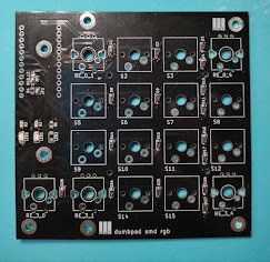
After more a week, the two black PCB sent for fabrications was finally back. Time to do some SMD soldering and figuring out on how to program the keyboard to work.
The RGB SVT source codes at Summary Links below.
 |
| SVT RGB dumbpad (front) |
 |
| SVT RGB dumbpad (back) |
QMK firmware
The Quantum Mechanical Keyboard ( QMK ) is an open source community centered around developing computer input devices. ( Text copied directly from QMK site )
It support a few commonly used micro-controller like Atmel atmega32u4, Freescale Teensy and STM32 families of micro-controllers. For my case, the Pro Micro uses the Atmel atmega32u4, a popular choice for Arduino that can emulate a keyboard / HID devices.
As I am just a fork of the dumbpad keyboard, I will also just need to modify the same keyboard by modifying the keymaps and config files only. The QMK does NOT use the Arduino IDE.
As my primary computer runs on Win 10 , I will choose the Windows development tools and downloaded the following software.
- QMK Toolbox
- MSYS2
- VSCode ( I already have this )
The MSYS2 installation was not as straight-forward as I expected but after a few trial and errors, installing and re-installing Python, I found the missing piece. Open a MinGW 64-bit Terminal, I repeat, a MinGW 64-bit Terminal.
Once everything was setup successfully, it is time to do some code editing.
git clone the qmk firmware from github.
Go to the keyboard/dumbpad folder and open the config.h file, edit it with your favorite text editor.
Figuring out the LED pins
As the pins are following the Atmel port pins instead of the Arduino digital pins, I have to map this according to the LED I connected to the Pro Micro.
I was using port B6 as LED0 and port B1 as LED1
LED2 at port B3 is shared between LED2 or RGB LED pin.
I also noticed there are two extra on-board LED at port B0 and port D5, let's configure them as well. As the Pro Micro is facing downwards, the two on-board LED, will only shine downwards and not very useful in every use.
Below are the config.h for the LEDs
/* LED layer indicators */
// Using external LED for layers indicator
#define LAYER_INDICATOR_LED_0 B6 // Red
#define LAYER_INDICATOR_LED_1 B1 // Blue or Green
// On-board LED for debugging
#define LAYER_INDICATOR_LED_2 B0
#define LAYER_INDICATOR_LED_3 D5
The next pin are the most exciting one, the RGB pins as below, you need to state the pin number and the number of LEDs on the LED strip. As I run them in mirror mode ( Both LED strip will display the same patterns, I just indicate 4 as the number of LEDs )
#define RGB_DI_PIN B3
#ifdef RGB_DI_PIN
#define RGBLED_NUM 4
The rest of the RGB animations / patterns can be customized according to your own needs.
Rotary Encoder
The next pins to configure is the rotary encoder, the dumbpad keyboard support TWO rotary encoder, I got both encoder working but the final version, I will only use one encoder.
I m using ENCODER0 connected to port D4 and B2.
ENCODER1 (unsued) is connected to port port D0 and D1
/* Rotary encoder */
// D1, D0 is right encoder
// D4, B2 is left encoder
#define ENCODERS_PAD_A { D4 }
#define ENCODERS_PAD_B { B2 }
Once all the config.h pin definition is done, I make a copy of the default keymap folder for my keyboard, I called it svt_numpad
Key Mappings
Edit the keymap.c file, the default already have all the keys mapped.
From here, you can change the keys according to the documentation from QMK here.
https://beta.docs.qmk.fm/using-qmk/simple-keycodes/keycodes_basic
RGB stuff here
https://beta.docs.qmk.fm/using-qmk/hardware-features/lighting/feature_rgblight
/*
BASE LAYER
/-----------------------------------------------------`
| | 7 | 8 | 9 | Bkspc |
| |---------|---------|---------|---------|
| | 4 | 5 | 6 | + |
| |---------|---------|---------|---------|
| | 1 | 2 | 3 | - |
|-------------|---------|---------|---------|---------|
| Play/Pause | TT(_SUB)| 0 | . | = |
\-----------------------------------------------------'
*/
[_BASE] = LAYOUT(
KC_P7, KC_P8, KC_P9, KC_BSPC,
KC_P4, KC_P5, KC_P6, KC_KP_PLUS,
KC_P1, KC_P2, KC_P3, KC_KP_MINUS,
KC_MPLY, TT(_SUB), KC_P0, KC_PDOT, KC_EQL
),
/*
SUB LAYER
/-----------------------------------------------------`
| | |RGB_M_SW | RGB_M_T | Numlock |
| |---------|---------|---------|---------|
| | | RGB_M_B | RGB_M_R | RGB_MOD |
| |---------|---------|---------|---------|
| | | RGB_HUI | RGB_HUD | RGB RMOD|
|-------------|---------|---------|---------|---------|
| MO(_DBG) | | RGB_VAI | RGB_VAD | RGB_TOG |
\-----------------------------------------------------'
*/
[_SUB] = LAYOUT(
_______, RGB_M_SW, RGB_M_T, KC_NLCK,
_______, RGB_M_B, RGB_M_R, RGB_MOD,
_______, RGB_HUI, RGB_HUD, RGB_RMOD,
MO(_DBG), _______, RGB_VAI, RGB_VAD, RGB_TOG
),
/*
DEBUG LAYER
/-----------------------------------------------------`
| | | | | Reset |
| |---------|---------|---------|---------|
| | | | | |
| |---------|---------|---------|---------|
| | | | | |
|-------------|---------|---------|---------|---------|
| | | | | |
\-----------------------------------------------------'
*/
[_DBG] = LAYOUT(
_______, _______, _______, RESET,
_______, _______, _______, _______,
_______, _______, _______, _______,
_______, _______, _______, _______, _______
),
};
Summary Links
Part 3 with additional modifications to support hotswap keys.


.jpg)


