When we discovered the Electric Imp recently, we almost immediately ordered them directly from US to do research and coding on them. You can read more about the electric imp on their websites or view their videos on Makerfaire, in short, it is a awesome product.
 |
| electric imp |
What it does is to simplify the Internet connectivity of electronic projects and the ability to program your device or "things" over the Internet on a web based IDE is a really powerful concept made into reality.
Before the Imp, a few other options existed to have your device "Internet Enabled" and they are either too expensive or requires a lot of other stuff like router / firewall configuration, having a linux box in between like the Raspberry Pi version of Raspbian or plug in an Ethernet Shield on top of an Arduino. I've tried them all out and could not find any other solution as simple as this.
Firstly, do not be confused by it SD card looking form factor, it is NOT a memory card but a powerful microcontroller plus wifi enabled radio all stuff into a tiny SD card otter shell. When it comes to connecting endpoints like smartphones and laptops to wifi, we are all aware of the trouble of choosing the correct access point and keying in the wifi password to gain access.
How do you key in the access point name and wifi password to this small little SD card microcontroller ? The answer is light or blinking lights to transmit these wifi authentication information directly to the card itself. They have mobile apps for both iOS and Android platform. View this video demo on how it works.
With the Internet connectivity issue easily solved using an Electric Imp, my next questions is what if I want to connect more than one device ? Should I buy another electric imp and the Imp development board to house it or should I find an alternative (or more cost effective ) method to link up all my other devices/things in the house.
With my other projects all using nRF24L01 radio, the choice is quite obvious for a wireless solution, find a nRF24L01 driver for the electric imp platform. After a few google searches, I manage to find an initial driver for the electric imp on the forum BUT it was totally not working and unfinished. This is what usually happens to open source and community projects, someone will write the codes when time and interests permits and abandon it when it is either not working or find something else more interesting project to do...
Since I have a little bit of experience forking the nRF24L01's RF24 library and making the RF24 drivers work for Arduino, Raspberry Pi and Atmel attiny85, I took up the challenge of writing the nRF24L01 driver for the electric imp at the same time learning a C like new object oriented programming language called Squirrel that was used on the Imp.
The nRF24L01 I wrote was a combination of RF24 codes with the Mirf codes as the Mirf codes was easier to understand and was originally written in C instead of C++ for the RF24. There were some issues on the SPI but with a help of a Logic Analyzer and Logic software, I was able to fix most of the SPI related issues
The github repo for the Electric Imp nRf24L01 driver is at https://github.com/stanleyseow/electricimp-nRF24L01. You can comment out all the debug output when everything the radio is running ok.
 |
| block diagram |
My next task is to find a useful application for my wireless solution, since I had a RGB LED strip and always like to make an Internet enabled RGB lighting, I hook up everything like the block diagram above. The web portion is a jquery colour picker from farbtastic with some touchscreen add-ons for touchscreen smartphone/tablets. Do viewsource to see the javacript codes at http://stanleyseow.asuscomm.com/color/.
 |
| colour picker |
The Arduino portion is a simple code to read the three RGB codes from the colour picker webpage via nRF24L01 in #RRGGBB in hex and convert them to decimal ( 0 - 255 ) for analogWrite to the PWM pins. I'm driving the 12V RGB LED strip using a ULN2803 IC similar to this page on ambient lighting.
 |
| Arduino + nRF24L01 + RGB |
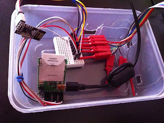
The electric Imp part of the hardware is an April development board with the Impee SD card with SPI pins connected to the nRF24L01 radio. Since both the Imp and nRF24L01 runs on 3.3V, I do not need power regulator for this.
 |
| Impee + nRF24L01 |
Those red mini hooks are connected to my logic analyzer when I was troubleshooting the SPI issues I faced earlier.
In summary, this seems like a complex setup but in actual fact after removing all the nRF24L01 library/drivers, the lines of codes is only the below :-
Imp Server Side :-
- ===============================================================================================
- Electric Imp agent side ( cloud / server side ) :-
- ===============================================================================================
- http.onrequest(function(req, resp){
- server.log("Got a HTTP request");
- if (req.method == "POST"){
- local body = http.urldecode(req.body)
- server.log(body.data);
- device.send("agentBuffers",body.data);
- //device.on(recvfromImp,impBuffer);
- }
- resp.send(200, "<head><meta http-equiv=\"refresh\" content=\"1;url=http://stanleyseow.asuscomm.com/color/\"><html>OK</html></head>");
- });
Imp device to send to nRF24L01 ( radio.send() ) :-
- ===============================================================================================
- Electric Imp device ( the white wifi SDcard in yr home ) :-
- ===============================================================================================
- function watchdog2() {
- agent.on("agentBuffers",function(value) {
- server.log("Got a buffer from agent/http");
- if ( value.len() < 33 ) { // Make sure nRF24L01 payload is only 32bytes or less
- radio.send(value,value.len()); // Send the payload to the radio
- }
- } );
- radio.powerRX();
- imp.wakeup(1, watchdog2 );
- }
Arduino portion after getting the #rrggbb from nRF24L01 :-
- HEXtoRGB();
- analogWrite(RED_PIN,r);
- analogWrite(GREEN_PIN,g);
- analogWrite(BLUE_PIN,b);
Summary Links :-
- Arduino RGB code http://pastebin.com/ZvtE1p9T


